Balling During PCB Rigid Flex
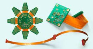
Printed circuit boards (PCBs) are crucial components of many devices. These circuits are made of a base material like polyimide or polyester and contain conductive materials etched in as many layers as the PCB design calls for. They are then covered with a coverlay that protects the layers from moisture and contaminants. Rigid flex is a variation of traditional rigid PCBs that incorporates flexible sections that allow the board to flex and bend during operation. It is commonly used in products that need to withstand high levels of vibration, shock and movement.
Rigid flex offers many benefits over traditional rigid PCBs, including lower weight and more space for mounting components in the flexible section. This type of flexible PCB can be used in a number of industries, including medical and automotive. Medical devices like pacemakers and cochlear implants are a good example of a device that could benefit from the use of a pcb rigid flex. Rigid flex is also commonly used in military missile guidance systems, cameras and video cameras, wearable electronics and vehicle infotainment systems.
The main drawback of a rigid flex PCB is that it can be more difficult to assemble and rework than traditional rigid PCBs. This is because it involves a longer production process and uses different handling, etching and soldering methods. This extra time and effort can add to the overall cost of the rigid flex circuit board.
Solder Balling During PCB Rigid Flex
In order to prevent solder balling during PCB rigid flex, a few important measures are taken. These include ensuring that there is sufficient flux in the solder paste, making sure that it is clean and that it has not been used past its expiration date, and ensuring that the stencils are cleaned and dry before printing. Moisture also contributes to the formation of solder balls, so it is vital that it be removed as much as possible during the fabrication process.
Other reasons for solder balling during pcb rigid flex include excess placement pressure, misalignment of the pads and tracks on the PCB, incorrect positioning of the IC packages or sockets and the presence of residues left from previous manufacturing processes. Solder bridging can also be caused by too little solder in the pads and too much in the traces.
Another issue is that of signal integrity and EMI control in the flexible regions of the circuit board. This can be challenging to achieve due to the varying thermal expansion coefficients of the different materials used in the rigid and flexible parts of the circuit board. In addition, improper transitioning of signals from the rigid to the flexible sections can cause impedance mismatches and poor signal quality. The best way to avoid these problems is to work with a printed circuit board fabricator early in the PCB design process. A company that has experience with rigid flex PCBs will be able to provide advice on these issues and help you to overcome them. This will ensure that your pcb rigid flex performs well in its intended application.